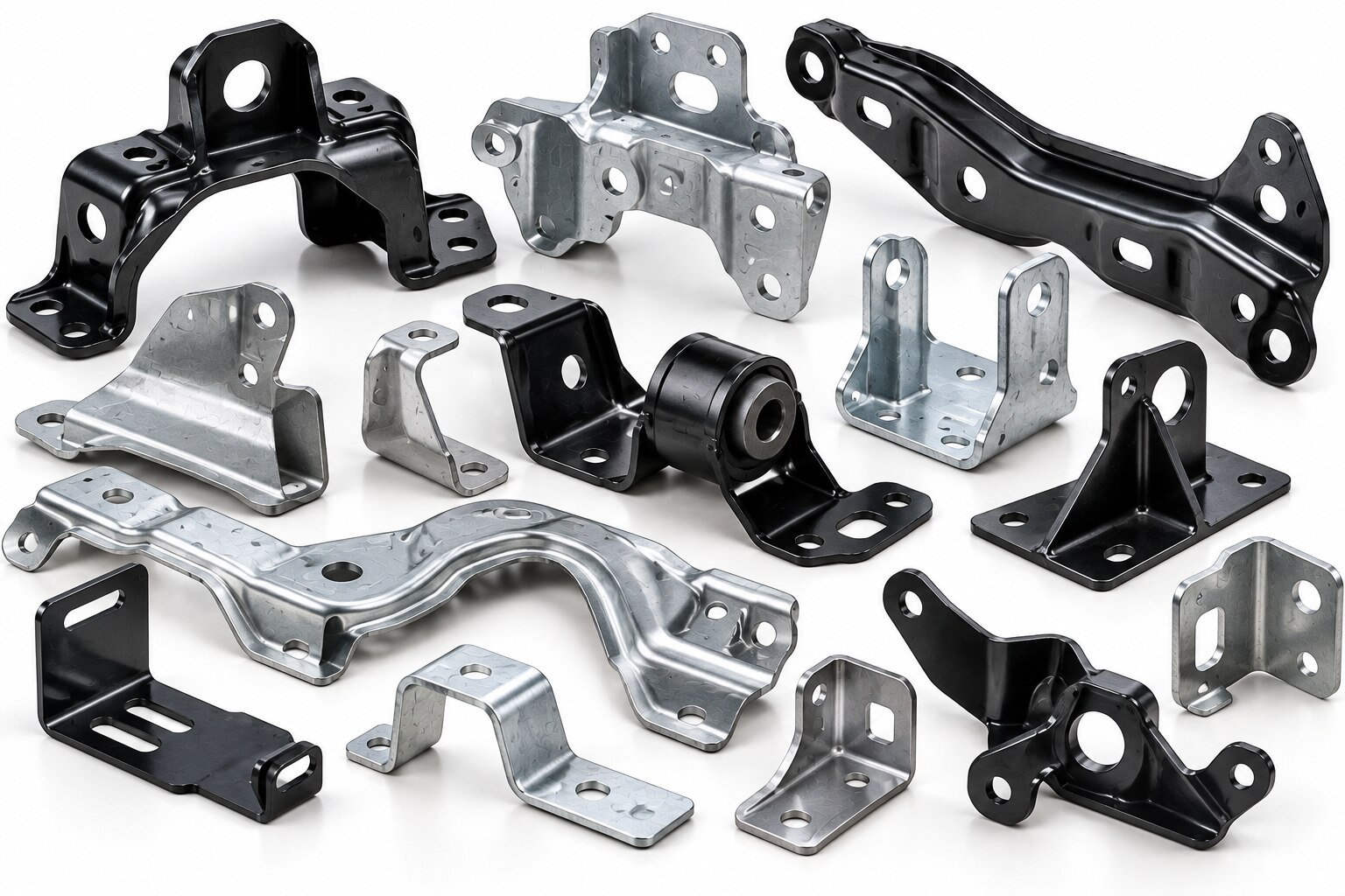
An automotive bracket must carry its assigned load, remain secure through vibration and temperature changes, fit the production assembly, and resist corrosion for its intended service life. By the end, you will be able to specify the bracket’s material, geometry, joint, validation tests, inspection records, and production method without relying on a catalogue name alone.
Key takeaways
- Classify the bracket as structural, locating, retaining, shielding or routing before designing it.
- Match material thickness and geometry to stiffness, fatigue loads and the service environment.
- Validate fasteners, welds, corrosion protection and fit together under production-like conditions.
- Control incoming parts against drawings, dimensions, material requirements and manufacturing-process limits.
Define the bracket’s function, loads and service environment
Classify the bracket before choosing its shape: structural, locating, retaining, shielding, or routing. A structural engine, battery, seat, or fuel-tank bracket needs a different automotive bracket load capacity from trim or cable-routing hardware.
| Type | Primary duty | Main failure concern |
|---|---|---|
| Structural | Carry component and vehicle loads | Yielding, buckling, fatigue |
| Locating | Hold position and alignment | Hole movement, tolerance stack-up |
| Retaining | Prevent release or displacement | Shock, fastener slip, pull-out |
| Shielding | Block heat, debris, or contact | Distortion, heat damage, rattling |
| Routing | Guide cables, hoses, or pipes | Chafing, fretting, detachment |
Define the static load from component weight and assembly forces, the shock load from impact or abrupt vehicle movement, and the repeated vibration load from road-induced excitation. Record attached mass, mounting orientation, thermal expansion, resonance risk, required safety factor, acceleration, frequency, duration, shock pulse, fatigue cycles, and acceptance limits on the drawing.
ISO 16750-3 provides the mechanical-load testing framework; the customer defines the bracket-specific limits.
Check the load path from component through bracket, fastener, vehicle body, and reinforcement. Testing the bracket alone can miss bolt-preload loss, joint slip, fretting, rattling, or fatigue at bend radii and weld toes. Match the test fixture to production stiffness, fastener torque, boundary conditions, and attached mass.
Record heat exposure near exhausts and engines, fuel or battery proximity, water, road salt, and contact with plastic parts. Do not infer vehicle application, tank capacity, mounting orientation, or interchangeability from labels such as 1 LTR or 3 LTR.
Select material, thickness and geometry for stiffness and fatigue life
The mild steel vs high-strength steel choice starts with load, mass and forming risk, not tensile strength alone.
Mild steel is economical and easy to form or weld; DP600 or another high-strength grade can reduce thickness and weight, but demands control of springback, edge cracking, local thinning, weld heat effects and hydrogen embrittlement after acid cleaning or plating.
| Material | Advantage | Main control |
|---|---|---|
| Mild steel | Low cost, easy forming and welding | Protect against corrosion |
| High-strength steel | Higher strength at lower mass | Control springback, cracking, welding and plating |
| Stainless steel bracket | Strong corrosion resistance | Accept higher material and forming cost |
| Galvanized steel | Zinc coating protects exposed sheet | Control coating at cuts, bends and welds |
| Aluminum bracket material | Low mass | Account for lower stiffness, joining changes, galvanic corrosion and fatigue |
Name the exact grade, sheet thickness, temper where relevant, finish and allowable thickness tolerance on the drawing. Examples include CR4, DP600, 304 stainless, Z275 galvanized coating or 6061-T6 aluminum; select them for the duty, not by label.
Set bend radius, flange width, hole diameter, slot length, hole-to-edge distance, bend angle, flatness and positional tolerances from the assembly stack-up. Use ribs, beads, gussets, wider flanges and shorter unsupported spans to prevent buckling and raise stiffness. Define functional tolerances from datums under ISO 1101.
Check natural frequency and mode shape against the vehicle excitation spectrum; no universal frequency limit fits every bracket. Measure formed holes and flanges after tool tryout, including bend sequencing, burr direction, springback, tool access and formed-hole movement.
Engineer joints, fasteners, welds and corrosion protection together
A bracket joint survives only when the interface controls movement, load transfer, access, and water. Confirm these details before releasing the drawing:
- Set mounting-hole position, bolt clearance, tool and fastener access, and mating-surface flatness from assembly datums.
- Maintain clearance from hoses, wiring, exhaust parts, fuel lines, batteries, and moving components.
- Provide drainage; eliminate crevices and water traps.
Specify automotive bracket fasteners by bolt grade, nut type, thread engagement, grip length, washer arrangement, retention method, and torque. Check whether tightening crushes thin sheet, bends a flange, or loses clamp load after coating settlement. Test slip, fretting, preload loss, and joint movement during vibration and thermal cycling.
For welded bracket design, define resistance or fusion weld type, weld size, length, spacing, access, electrode condition, current, force, weld time, distortion limit, and weld-to-edge distance. Inspect fusion welds against a stated ISO 5817 quality level; resistance welds need process-specific acceptance criteria.
Coating choice must match the service:
| Option | Strength | Main concern |
|---|---|---|
| Zinc plating | Thin, economical | Damaged edges and heat |
| Hot-dip galvanizing | Thick sacrificial protection | Distortion and formed-edge coverage |
| E-coating | Uniform vehicle-body coverage | Repair after welding or damage |
| Powder coating | Durable barrier | Cut edges and chips |
| Stainless-steel passivation | No applied coating | Cost and galvanic corrosion |
Protect cut edges and weld heat-affected zones. Separate dissimilar metals or use compatible coatings, because galvanic corrosion accelerates when aluminum, steel, stainless steel, fasteners, or coated panels contact in saltwater.
Fit-check the design and validate it under production-like conditions
Begin with the approved drawing revision, then record datum points, hole-center coordinates, slot geometry, flange locations, and the complete 3D envelope. For an automotive bracket fit check, compare the part with the vehicle assembly or a production-intent fixture. Check fastener insertion, tool clearance, mating-surface contact, installed clearance, component movement, and drainage.
Check each feature against a defined method and consequence:
| Feature or condition | Verification method | Reject when |
|---|---|---|
| Hole position and flange location | Coordinate-measuring machine or functional gauge | Fasteners bind or the interface misses its tolerance |
| Flange angle, flatness, thickness and slot length | CMM, gauge, and calibrated hand tools | Clamping distorts the joint or mating surfaces do not seat |
| Burrs, sharp edges, cracks and deformation | Visual inspection and magnified examination | The part can cut, crack, interfere or lose shape |
| Coating coverage and weld appearance | Coating inspection and defined weld criteria | Bare edges, peeling, porosity, undercut or distortion appears |
Validate actual failure modes, including static overload, repeated fatigue, vibration, shock, thermal cycling, corrosion, torque retention, and resonance. Apply ISO 16750-3 mechanical-load methods where relevant, but set the bracket’s acceleration, duration, cycles, temperatures, and acceptance limits for the vehicle joint.
Match fixture stiffness, fastener torque, boundary conditions, and attached mass; an overly rigid or light fixture can conceal failure or exaggerate it.
Use ISO 9227 salt spray to compare a specified corrosion system, while defining exposure duration and corrosion limits separately. PPAP bracket validation must use production-intent tooling, material, operators, and controls, supported by:
- PFMEA, control plan, measurement-system analysis, and capability data
- Weld records and inspection results
- Traceability to material, coating, tooling, and engineering revision
Choose the manufacturing route and control incoming parts
Choose the route that matches volume, geometry, load path and tolerance rather than copying a catalogue shape.
| Route | Best fit | Main control |
|---|---|---|
| Laser cutting and bending | Prototypes, low volumes, frequent revisions and complex flat patterns | Control bend sequence, springback, burr direction and repeatability |
| Stamping or progressive tooling | Higher volumes and stamped automotive brackets | Justify tooling through cycle time, consistent geometry and lower unit cost |
| Welded assembly with welding fixtures | Separate flanges, gussets or mounting features simplify forming | Control distortion, weld access, spacing and inspection |
| Machined plate | Low-volume precision interfaces or heavy sections | Control datum location, flatness and machining cost |
| Casting | Complex three-dimensional load paths at larger volumes | Control porosity, tooling and dimensional shrinkage |
| Formed wire | Light retaining or routing duties | Reject it when the bracket carries structural load |
Use laser cutting and bending when prototype vs production tooling economics favour flexibility. Use stamping after demand justifies die investment; a progressive die can reduce unit cost but makes design changes expensive. Specify production measurements for hole coordinates, flange angle and formed features because springback, thinning and edge cracking can shift the delivered part.
Reject a generic catalogue bracket for crash relevance, severe fatigue, high heat, fuel contact, tight positional tolerances or unusual corrosion exposure. Shankar Spring And Coil Works becomes a useful supplier when you provide the drawing revision, material grade, thickness, finish, datums, tolerances, load cases, weld requirements, inspection plan, packaging controls and change-control rules.
Your incoming inspection checklist should verify:
- Revision, material certificate, thickness, hole coordinates and flange angle
- Burrs, cracks, deformation, coating coverage and weld condition
- Packaging damage, lot traceability to material heat, tooling, coating and inspection records
- IMDS, ELV and REACH declarations after approved material or process changes
Related products
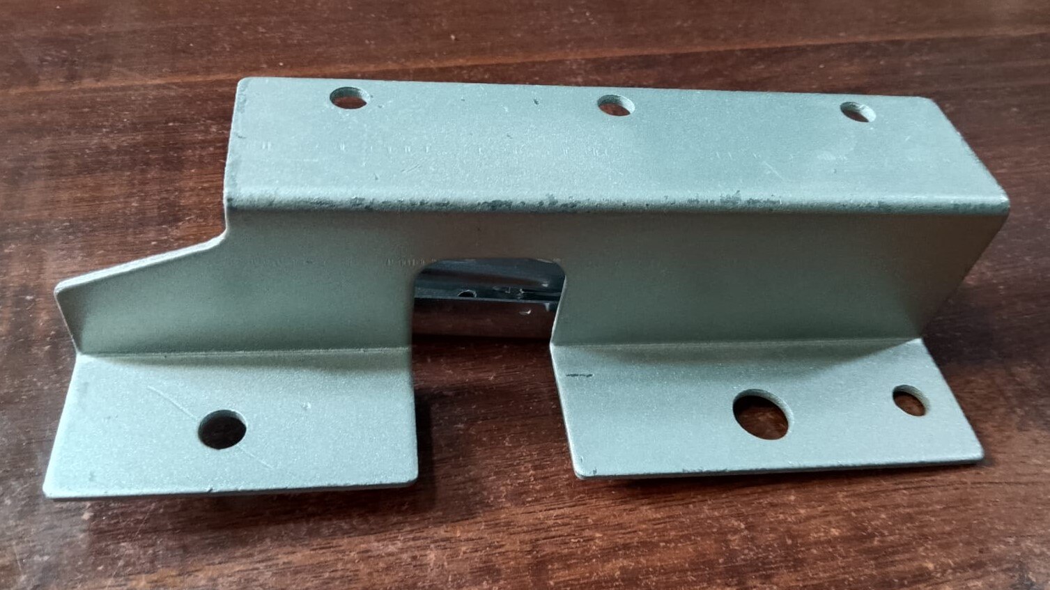 | Z Bracket 3 LTR Z Bracket 3 LTR View product → |
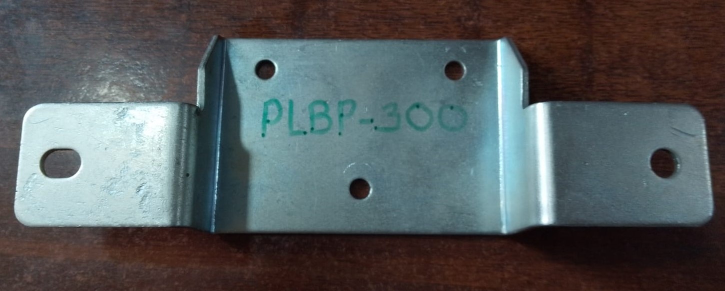 | 1 LTR Fuel Tank Bracket 1 LTR Fuel Tank Bracket View product → |
Frequently asked questions
How do you define an automotive bracket’s design requirements?
Classify its function first, then document loads, attachment points, vibration, temperature, moisture, chemicals and available space.
How should you choose material, thickness and geometry for a vehicle bracket?
Select them together to provide the required stiffness and fatigue life without creating unnecessary mass, interference or forming difficulty.
What must be considered when designing bracket joints?
Evaluate fasteners, welds, load transfer, access for assembly, joint movement and corrosion protection as one system.
How do you validate an automotive metal bracket before production?
Perform dimensional fit checks and test the bracket under production-like loads, vibration, temperature and assembly conditions.
How do you control the manufacturing quality of automotive brackets?
Choose a suitable forming, stamping, welding or machining route, then inspect incoming parts against approved drawings and material requirements.
Related products
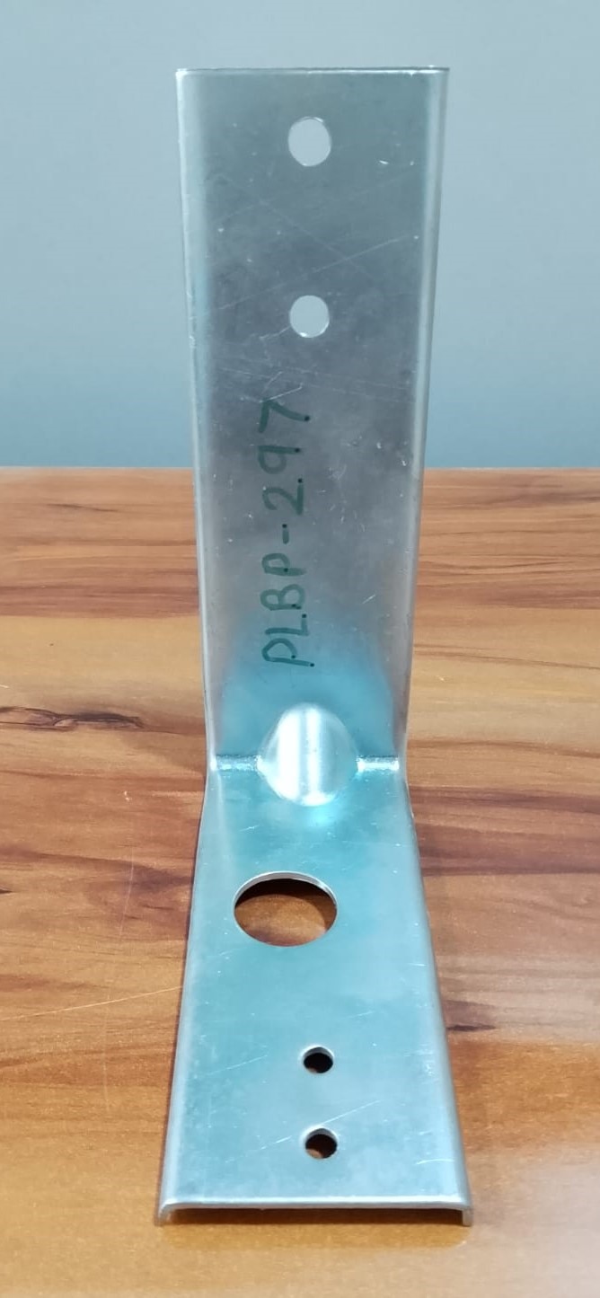 | L Bracket L Bracket L Bracket |
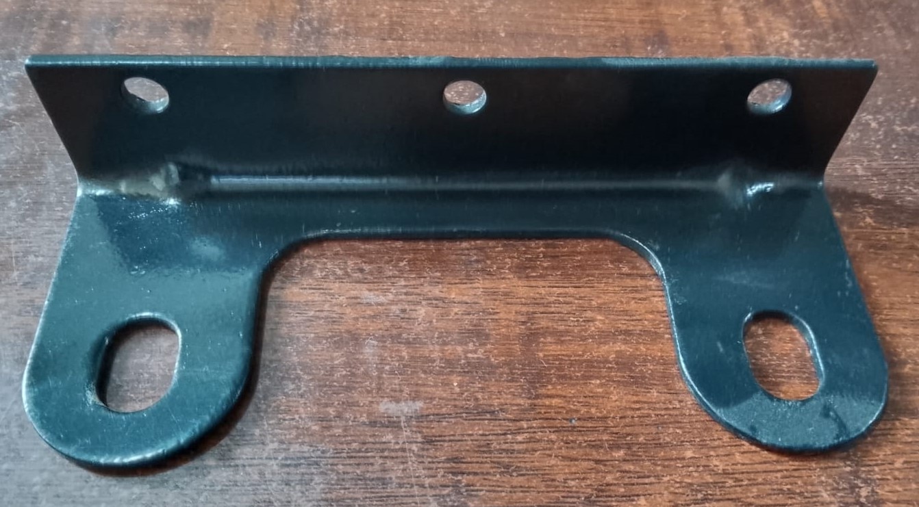 | Bracket (BIG) ) ( 3 LTR Tank) Bracket (BIG) ) ( 3 LTR Tank) View product → |
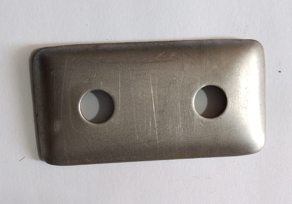 | Metal Plate Metal Plate View product → |
 | Bracket (DSK) Bracket (DSK) View product → |